I spent several days last week working on the new treadle hammer. It is coming along good and so far I have about three full days of work in it.
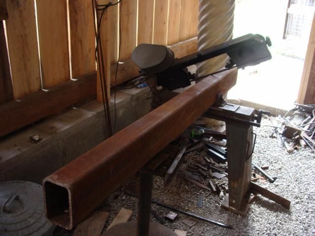
First thing, I set the bandsaw to work, cutting the major parts. Here the saw is working on cutting a piece of 4-inch by 6-inch tubing. The sides of the tube are one quarter inch thick. It took about forty minutes to make the cut. This piece is going to be the backbone of the entire hammer.
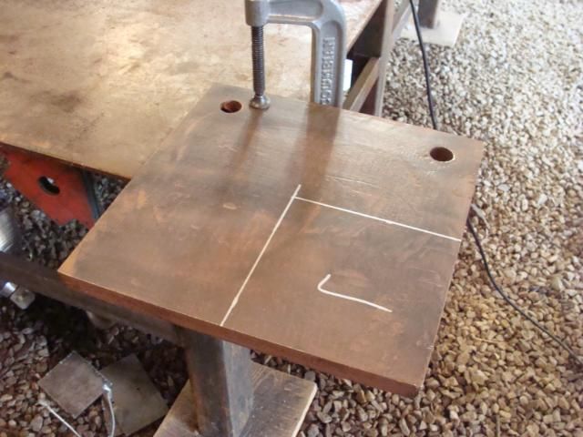
Here is one of three piece of 3/4-inch plate that I bought. This one is going to be cut into the hammer "dies"....the working surface of the hammer. One of the other plates is going to be the base plates under the backbone and the "anvil" part of the hammer. The new cutting torch made short and easy work of cutting these plates to the correct sizes. It's AWESOME when you have the right tool for the right job. PRAISE THE LORD for hooking me up with the deal I got on the torches.
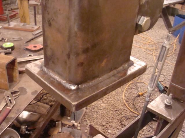
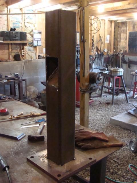
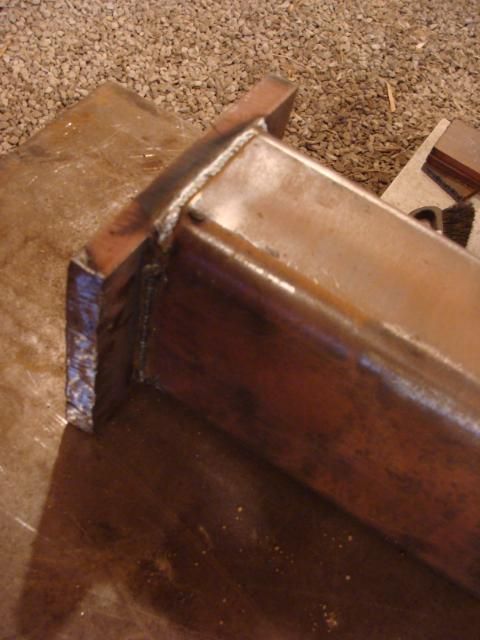
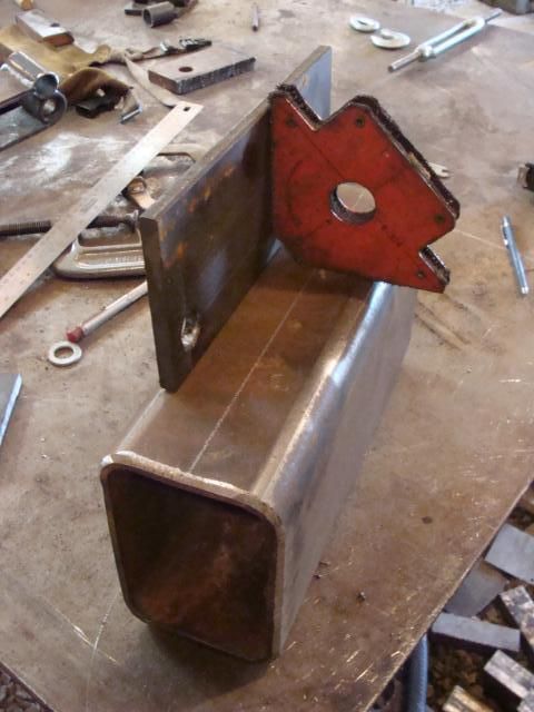
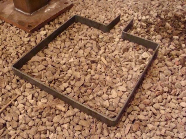
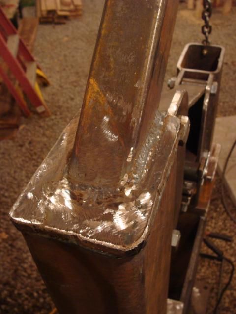
This is the "anvil" post for the hammer. This post is going to be the one taking the beating. It is 5-inch square tubing with 1/4-inch thick walls. There is a place cut into the side so that if I drop a tool down the tube by accident, it doesn't fall down the tube, instead it comes out the side. I've just started welding one of the 3/4-inch plates to the base of the anvil post in this picture.
I also welded a smaller plate to the base of the hammer backbone.
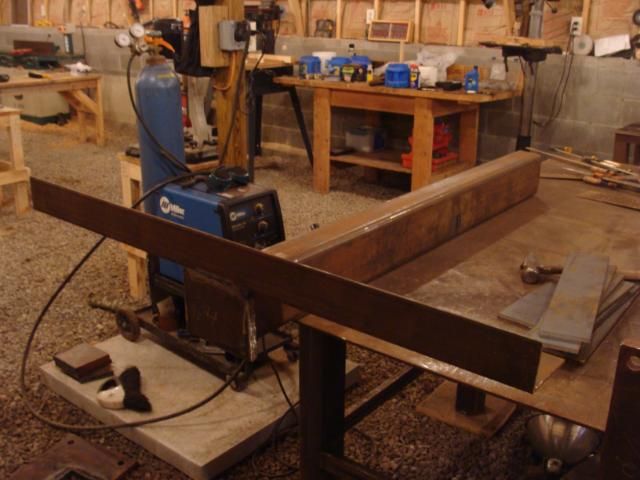
The backbone also got a long, heavy piece of angle iron welded to it. This gives the hammer overall stability.
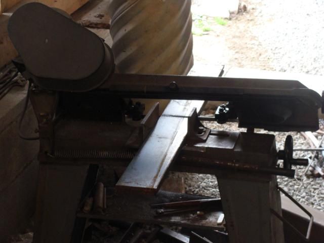
While I was welding all of that stuff together, I kept the bandsaw working on cutting other pieces. Here it is cutting one of the brace pieces. The braces are 3/8-inch by 4-inch flat bar. It took about 15 minutes to cut two brace pieces.
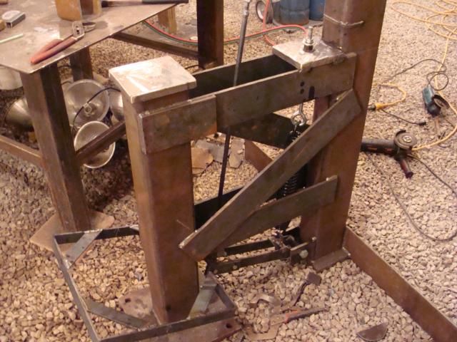
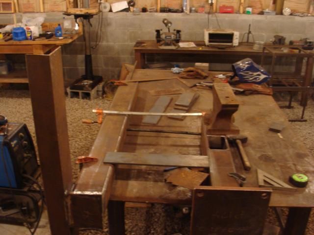
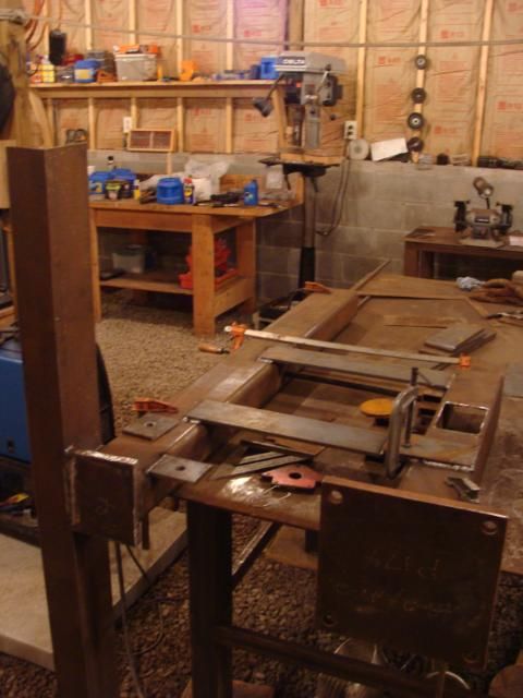
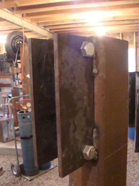
Once I had enough braces cut, I lined up the anvil post and backbone. This is a VERY critical stage. The backbone and anvil post have to be exactly parrallel, and lined up in all directions. This stage could literally ruin the hammer if something wasn't lined up right. The braces should be perpendicular to the backbone and the anvil post as well. This picture shows the anvil post and backbone clamped and weighted down.
Once everything was positioned, checked, double checked, and triple checked, it was ready to weld.
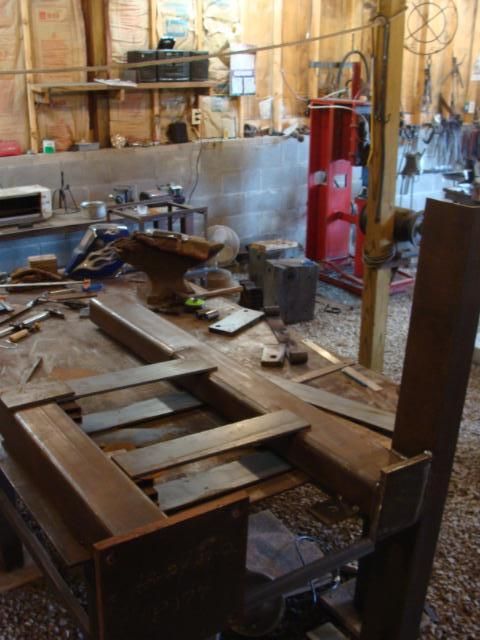
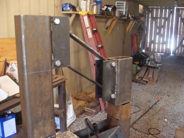
Once I finished one side of the hammer, I flipped it over and welded the bracing to the other side.
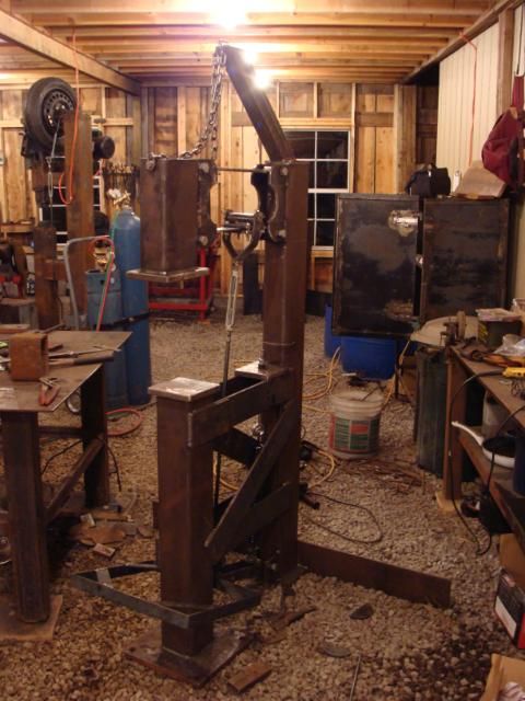
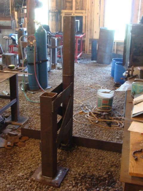
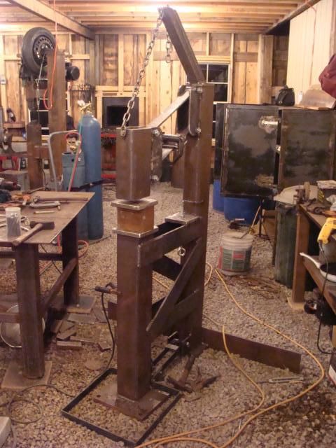
After all the bracing was welded in place, the hammer came off of the table and got set upright.
Once the bracing was in position, I mounted the attachment points for the foot pedal that will operate the hammer.
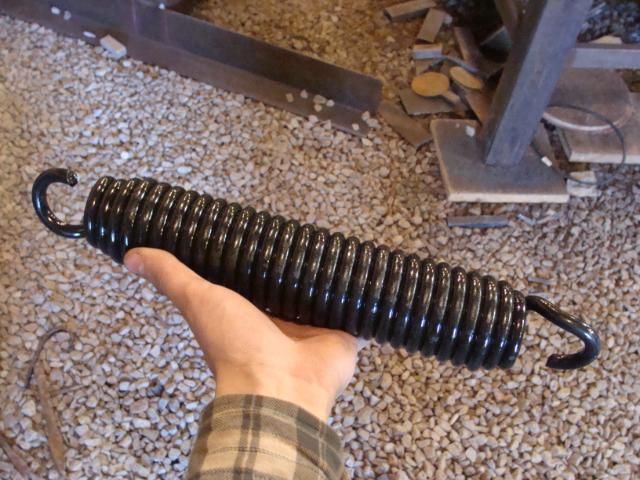
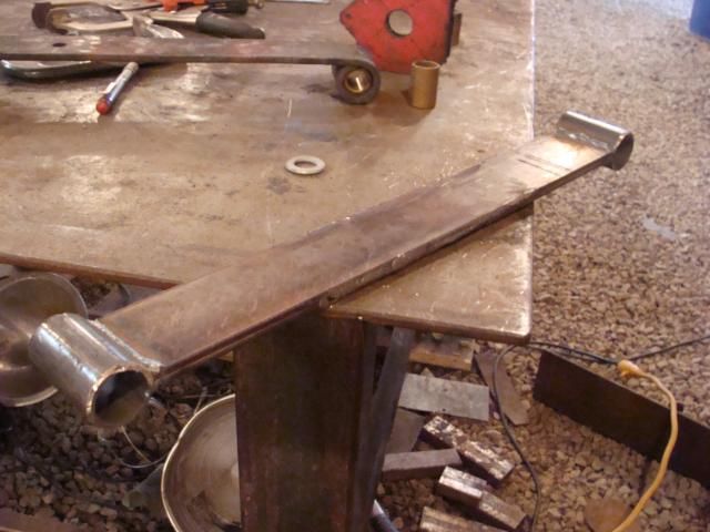
I needed a sort of custom leaf spring for the hammer. I got a price quote on the spring I needed and it was going to be around $150. NOT within my budget for this hammer. So, I took a piece of an old leaf spring (Complements of
CHASE SAXTON,) and made my own spring. It looks good, but I'll only be able to tell if it works by using the hammer.
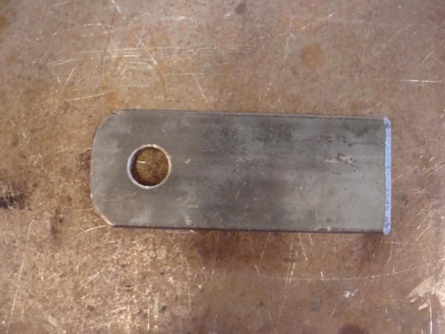
I needed a second piece, the same size as the spring, but it didn't have to be spring material. Just any old material would be fine. So this is the piece I made.
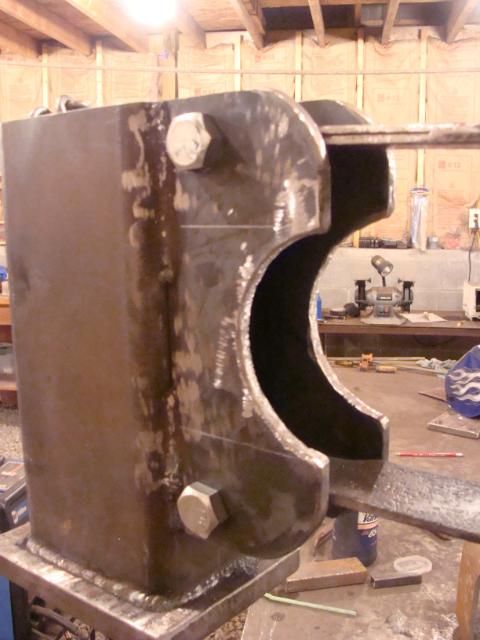
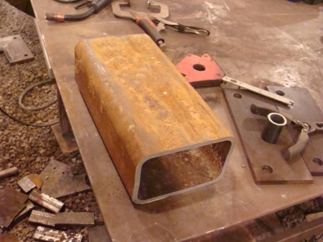
I cut the hammer head out of a piece of the 4x6-inch tubing. The hammer head is 12inches long.
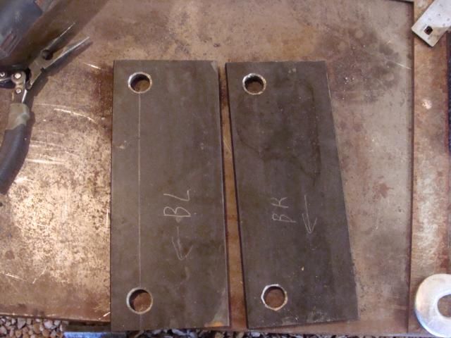
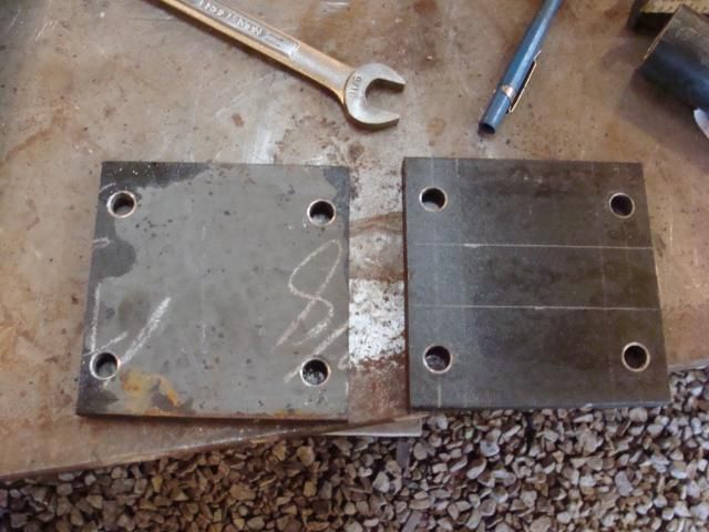
I also cut and drilled four of these plates. These plates attach the hammer head to the backbone. They are cut from some of the extra 3/8x4-inch flat bar.
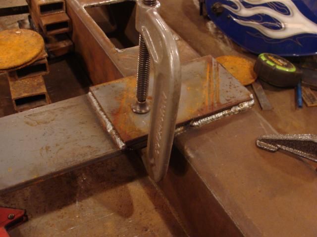
Here are one of the above pieces getting prepped for welding.
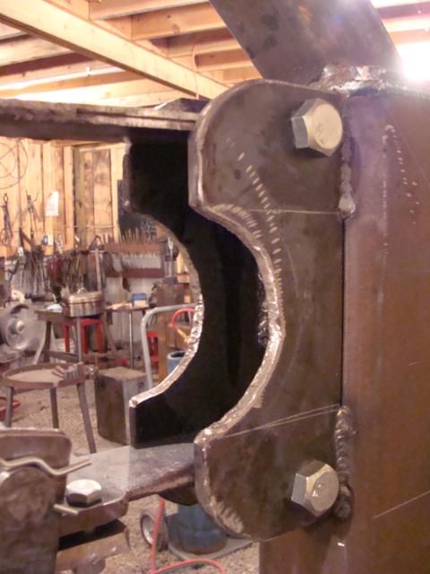
Here are the pieces once they were welded on.
This shows how they connect the hammer head to the backbone. The spring I made is on the bottom, and the twin piece to the spring is on the top.
There will be a second spring on the hammer, and this is where that spring will connect.
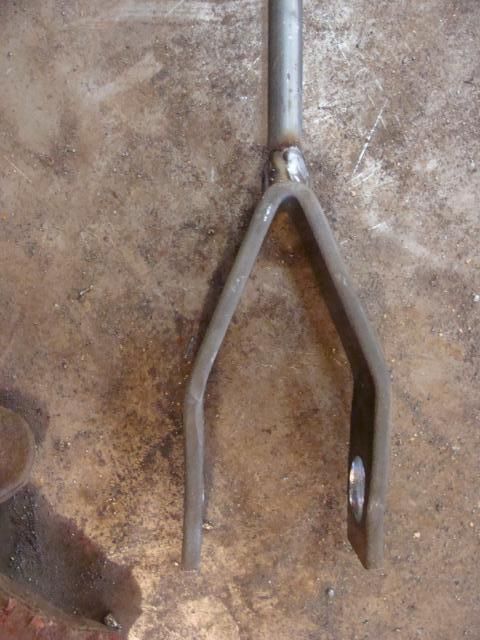
These plates here are part of a piece that will connect the hammer head to the foot pedal. I started by cutting and drilling two identical plates.
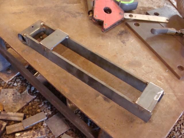
Then I welded a pipe on one.
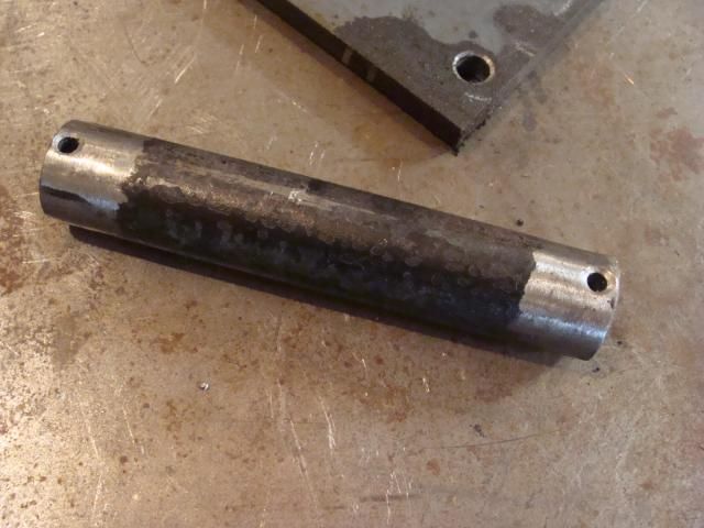
Then I cut a pin to fit in the pipe.
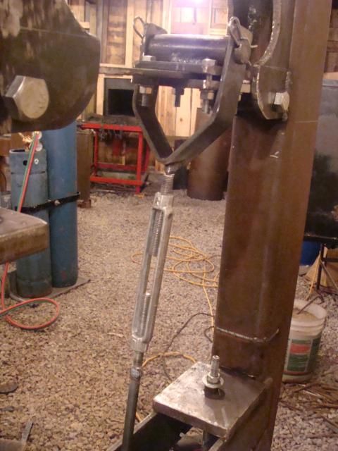
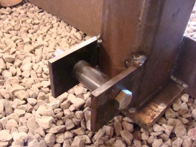
Then I made a piece that fit on the pin, assembled the entire thing, and bolted it to the spring a made earlier. There will be a rod welded to the bottom of this piece. That rod will go down to the foot pedal or "treadle." (This is a "treadle hammer.")
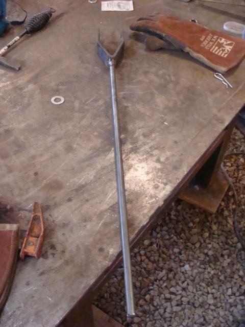
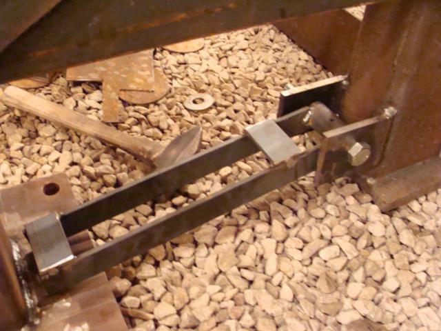
So then I had to make the treadle. The treadle was made in two main pieces. The first piece was the pivot arm.
The second piece was the treadle itself.
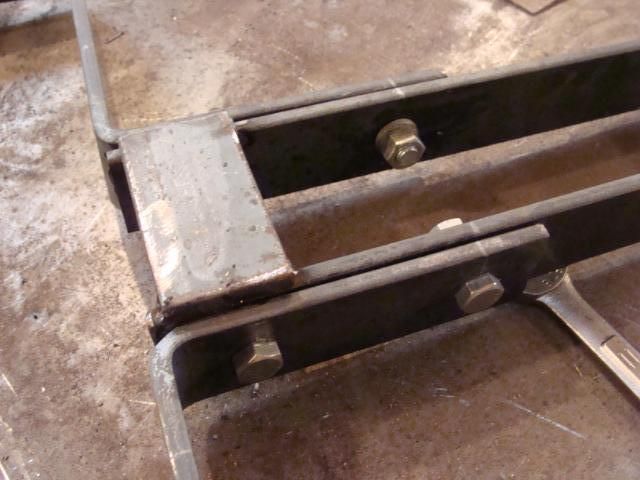
These two pieces bolt together.
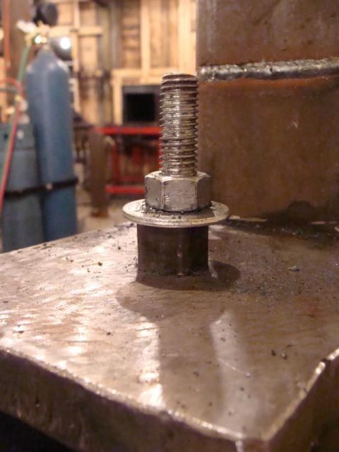
Then they bolt to the treadle attach pieces that are welded onto the backbone.
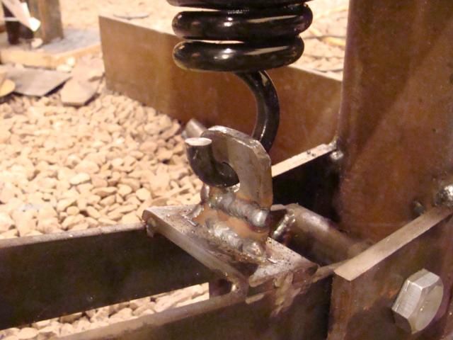
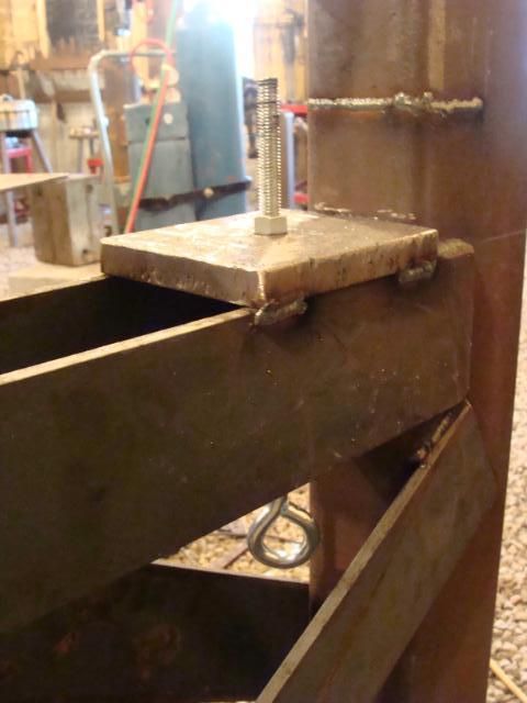
Once the treadle was in place, I needed a similar bracket there, like I put on the spring. I mentioned that the bracket on the spring would be attached to the treadle. Here is the bracket I made and attached to the treadle.
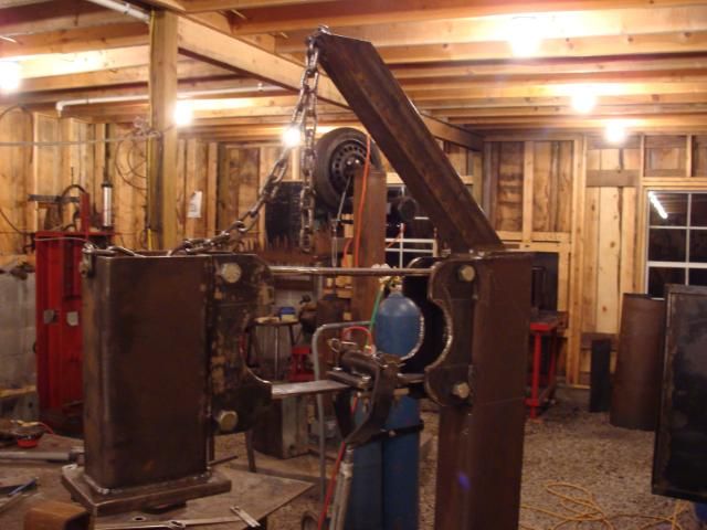
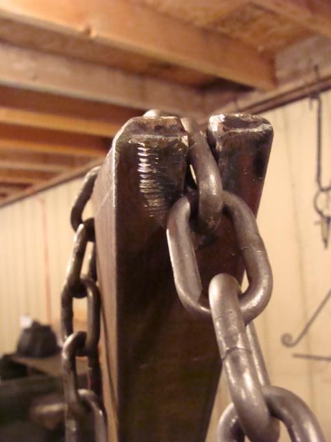
Once all of that was done, I needed to turn my attention once again to the hammer head. On this particular hammer, I will be working with my hand under the hammer head. The hammer head weighs about 30 - 40 pounds, so if I slipped even the slightest bit, my hand would be crushed. To prevent this, a heavy safety chain is attached to the hammer head. It is designed to restrict the hammer head so that if you do slip, the hammer head is caught well before it hits your hand. There is a large bar that is welded to the top of the hammer's backbone that holds this chain.
I cut a plate to weld around the safety bar. This gives the hammer a more finish look, and also strengthens the safety bar. This is the plate.
Once everything fit correctly, I welded it all in place.
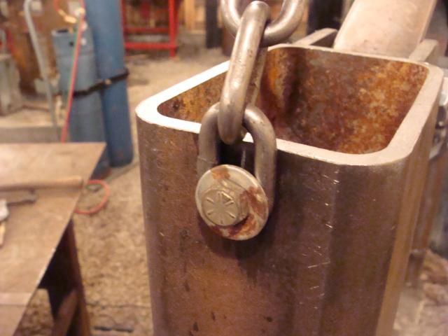
I drilled a hole in the hammer head and bolted the chain on there.
The chain fits in a slot in the safety bar, so that the chain can be removed and placed at whatever length is needed.
It holds the hammer head like this.
I am now just waiting on the second spring to arrive in the mail to finish the last few pieces on the hammer. I believe I'll have it up and functional by the end of the week.